")
")
| Issue |
Rev. Fr. Geotech.
Number 175, 2023
|
|
|---|---|---|
| Article Number | 8 | |
| Number of page(s) | 9 | |
| DOI | https://doi.org/10.1051/geotech/2023012 | |
| Published online | 23 octobre 2023 | |
Article de recherche / Research Article
An adaptation of Limit Equilibrium Methods for the design of soil-nailed walls facings
Une adaptation des méthodes d’équilibre limite pour le dimensionnement du parement des murs en sol cloué
Univ Gustave Eiffel, Univ Lyon, GERS-RRO, F-69675 Lyon, France
* Corresponding author: Cette adresse e-mail est protégée contre les robots spammeurs. Vous devez activer le JavaScript pour la visualiser.
Abstract
Soil nailing is a technique developed in France during the 1970s for the retainment of excavations. The nails are steel bars introduced in the soil and preventing the soil mass to fail. Such structures are often designed through classical slope stability analysis software, i.e. based on Limit Equilibrium. The tension in the nails is generally considered equal to the maximum tensile forces admissible in the reinforcement. Yet, the service loads in the reinforcements are generally smaller than the calculated ones, especially at the bottom of the excavation because of the construction phasing. This is critical for the design of the facing and Limit Equilibrium based software need to be adapted by considering the construction phasing to modulate the mobilization of reinforcements. Based on the study of soil nailed walls through real-scale experiments, centrifuge and numerical modelling, an improvement of the limit equilibrium classical design is proposed. The software used was PROSPER, developed by Laboratoire Central des Ponts et Chaussées in the 1990s. The particularity of PROSPER is to derive the reactions of the nail by imposing a displacement of the failing soil mass. This displacement is generally considered as homogenous along the failure surface. However, considering a high displacement for the top nails (fully mobilized) and a small one for the bottom nails (partially mobilized) provide a relevant distribution of soil nail tensile forces. A distribution is proposed for such displacement and this design approach has been tested on an experimental wall, providing an efficient and time-saving design of soil-nailed walls.
Résumé
Le clouage des sols est une technique développée en France dans les années 1970 pour le soutènement des excavations. Les clous sont des barres d’acier introduites dans le sol afin d’empêcher la masse de sol de céder. Ces structures sont souvent conçues à l’aide de logiciels classiques d’analyse de stabilité des pentes, basés sur des méthodes d’équilibre limite. La tension dans les clous est généralement considérée comme égale à la tension maximale admissible dans les armatures. Pourtant, les charges de service dans les armatures sont généralement plus faibles, en particulier au fond de l’excavation en raison du phasage de la construction. Ceci est critique pour la conception du parement et les logiciels basés sur l’équilibre limite doivent être adaptés en modulant la mobilisation des renforcements. En se basant sur l’étude des murs cloués au travers d’expériences à échelle réelle, de modèles réduits centrifugés et de modélisation numérique, une amélioration de cette méthode de dimensionnement est proposée. Le logiciel utilisé est PROSPER, développé par le Laboratoire Central des Ponts et Chaussées dans les années 1990. La particularité de PROSPER est de déterminer les efforts dans les clous en imposant un déplacement de la masse de sol en rupture. Ce déplacement est généralement considéré comme homogène le long de la surface de rupture. Cependant, en considérant un déplacement élevé pour les clous supérieurs (entièrement mobilisés) et un déplacement faible pour les clous inférieurs (peu mobilisés) on obtient une distribution pertinente des tensions des clous. Une distribution de ce déplacement relative est proposée et cette nouvelle approche a été testée sur un mur expérimental, fournissant un dimensionnement efficace et rapide des murs cloués dans le sol.
Key words: soil nailing / limit equilibrium / facing design / skin friction mobilization
Mots clés : clouage des sols / équilibre limite / dimensionnement du parement / frottement mobilisé
© CFMS-CFGI-CFMR-CFG, 2023
1 Introduction
Developed in France in the 1970s, soil nailing is a technique for stabilizing slopes by reinforcing them with metal inclusions. Unlike reinforced earth, soil nailing is carried out on the soil in place and the slope is obtained by successive lifts (Fig. 1). These retaining structures are both cost effective and robust, even regarding seismic loadings (Tufenkjian and Vucetic, 2000). Nails are here passive anchors: they have no pretension and they retain the soil mass by friction when it starts to fail. Generally, a hole is drilled and the nail is placed in it before a cement grout is injected around it. However the use of so-called self-drilling nails (Mickovski et al., 2016) is becoming more widespread. To retain the superficial loose soil masses and prevent erosion, a facing is put in place. This facing also allows soil containment. It is traditionally made of steel lattice reinforced shotcrete. The nail heads are attached to the lattice and drains are installed at the back of the facing to avoid pore pressure accumulation. Although soil-nailed walls have been widely studied, the design of the facing still raises questions.
The first experimental soil-nailed wall was built for the German National Project Bodenvernagelung (Gassler, 1987) and showed that the resulting earth pressure on the facing is nearly 50% of the active Coulomb wedge. Within the framework of the French National Project Clouterre, three structures were built (Plumelle, 1987). It allowed to observe the location of maximum traction of the nails when the wall failed. The distribution of pressure behind the facing was also deduced from the forces measured in the nails. The distributions obtained in these two cases are compared in Figure 2a. The one observed by Gassler is pear-shaped when the one observed by Plumelle is rounder. This can be explained by the difference in nail lengths (3 m for a 6 m high wall in Bodenvernagelung and 7 m for a 7 m high wall in Clouterre). In this document, we call slenderness ratio the ratio B/H between the length of the nails B and the height of the wall H. Its value was equal to 0.5 in Bodenvernagelung and 1 in Clouterre.
In the United States, the Federal Highway Administration (FHWA) has also instrumented several soil nailed walls (Byrne et al., 1996) and the measured nail head forces are shown in Figure 2b. The most rigid walls (polyclinic and Swift Delta) show a distribution close to the one observed within Clouterre. It should also be noted that the IH-30 walls were built with flexible facings.
In 2008, a tunnel project for the Port of Dublin was an opportunity to set up a monitoring of the structure (Menkiti and Long, 2008). The experiment highlighted the important role of phasing in the development of tension in the nails and the very low stress on the lowest nail. Similar observations were made through the instrumentation of railway soil nailed wall in the Pretoria area (Jacobsz and Phalanndwa, 2011). It appears from this study that the nth nail is mainly mobilized by the n + 1th and n + 2th lifts.
Some centrifuge models have also been studied (Shen et al., 1982; Stewart, 1989; Jacobsz, 2013; Viswanadham and Rotte, 2015). The first one to take into account the construction phasing (Tei, 1993) measured pressures on the facing similar to the one observed by Plumelle or Gassler.
All traditional methods for the design of soil nailed walls are derived from slope stability calculations. A detailed presentation of this calculation can be found in (Raulin et al., 1974). There are many methods of slope stability analysis but they are all based on the computation of limit equilibrium of a failing soil mass. Thus they rely on the consideration of a failure surface. Coulomb (1773) first proposed a straight line. The circle was adopted in 1927 with the Fellenius method and is still used. Other surfaces such as the cycloid (Frontard, 1922) or the logarithmic spiral (Rendulic, 1935) are used. The last one has been popularized in the context of yield design (Salençon, 1983) where it provides the optimal upper bound for the resistant power by admitting a Mohr–Coulomb criterion and rigid body displacements. For every failure surface considered, the ratio between driving forces (weight of the soil mass, supported loads, …) and stabilizing forces (shear resistance of the soil, …) is computed.
For the design of soil nailed walls, stabilizing forces must include the contribution of the nails. It is generally done by using the multi-criteria calculation (Schlosser et al., 1984) whose principle is to calculate the maximum normal force Tn and shear force Tt the nail is able to provide. The four criteria considered are the steel failure, the nail pull-out, the yielding of the soil and the development of a plastic hinge in the nail. In the tension–shear force plane, the inner envelope of these criteria gives a mixed failure criterion and the design of the structure is carried out assuming that each nail is on this criterion. The values of Tn and Tt are determined by using a principle of maximum work. In practice, the criterion is often very flattened and the design dictated by Tn rather than Tt (Gigan, 1986).
In the PROSPER software, developed by Laboratoire Central des Ponts et Chaussées (Delmas et al., 1986), another method has been introduced to ease the identification of oversized or undersized nails. The determination of the forces no longer assumes that the inclusion (or the soil) is at failure. The principle, illustrated on Figure 3, is to assume a displacement δ of the failing soil mass and to derive the shear and bending forces induced in the nails by this displacement using beam theory. In this method, δ is considered aligned with the failure surface for every nail, which is at variance with a rigid block movement and with the yield design theory. The main role of δ is thus to mobilize the nail. The greater the relative displacement δ, the greater the reaction forces induced in the nail and the more the nail is mobilized. The method hereby described is sometimes called “displacement method” but since the word displacement can induce confusions and since, to the author knowledge, it has only been implemented in PROSPER, it will be called “PROSPER method” in this document.
It should be mentioned that limit equilibrium methods respecting the framework of yield design have also been developed. Among them, the homogenization method provided a reliable assessment of soil-nailed walls stability (de Buhan and Salençon, 1993). However this method, in essence, does not provide information on the tension of individual nails.
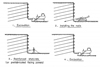 |
Fig. 1 Construction phasing of a soil-nailed wall (Schlosser et al., 1993). Phasage de construction d’un mur en sol cloué (Schlosser et al., 1993). |
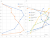 |
Fig. 2 (a) Comparison of the stress profiles measured by Gassler and Plumelle. (b) Stress profiles measured on the walls instrumented by the FHWA (Byrne et al., 1996). Tmax is the maximal nail head tension on the wall height. (a) Comparaison des profils d’effort mesurés par Gassler et par Plumelle. (b) Profils d’efforts au parement mesurés sur les murs instrumentés par la FHWA (Byrne et al., 1996). Tmax est la tension au parement maximale mesurée sur la hauteur du mur. |
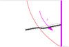 |
Fig. 3 Principle for determining the contribution of nails in PROSPER. Principe de détermination de la contribution des clous dans PROSPER. |
2 Importance of the construction phasing
An important aspect mentioned in the literature review is the importance of the construction phasing. In Clouterre, it was already observed that the earth pressure on top of the facing exceeds the earth pressure at rest but the one on the bottom of the facing is clearly lower than the active earth pressure. This transfer of load from bottom to top was then explained by the absence of displacement at the toe of the wall. As long as the next lift is not excavated, the soil at the bottom of the structure is constrained in displacement and cannot mobilize the nail. The soil mass is therefore retained by the forces mobilized in the upper nails. One must notice that the distribution presented by Plumelle is atypical since the top nail has broken but this progressive mobilization of nails along the excavation process has been confirmed by the later experiments and in situ observations.
To characterise the impact of construction phasing on the soil-nailed walls behaviour, a parametric study was carried out using centrifuge modelling. The experimental protocol is fully described in (de Sauvage et al., 2019) and the main results are presented in (de Sauvage et al., 2021). The excavation in front of a beforehand set up facing was realized inflight using geotextile baskets gradually wrapping around the axis of a motor (Fig. 4). The inclusions in the central profile were replaced by Bragg grated optic fibres bounded to a metallic conduit. It allowed to highlight the progressive mobilization of nails along the excavation process (Fig. 5). In particular, the bottom nail is hardly mobilized.
The container in which the model was realized has a translucid face and the use of an image-based technique called GeoPIV (Stanier et al., 2015) allowed to observe failure mechanisms of soil-nailed walls. In Figure 5, the relative norm of the strain tensor is plotted. It reveals two areas of high strains. The one figured by a solid grey line draws a Coulomb wedge whose obliquity (counted from horizontal) is close to  . The second, figured by a dashed grey line, is less marked, starts from the toe of the wall and goes up with a slightly different angle. A careful look at the displacement field suggests a logarithmic spiral rather than a straight line (de Sauvage et al., 2021).
These observations as well as the magnitude of discontinuities in the displacement field suggest the presence of nested slides, increasingly active from right to left. This complex kinematics can partially explain the tension pattern in the nails. Indeed, the maximum tension in nail C2 after the lift 3 is closer to the facing than in nail C3, which is at variance with a monoblock displacement. When the wall reaches failure, the tension distribution in C2 does not present a clear maximum. It seems that C2 is mainly mobilized by both failure surfaces, whereas C3 is mainly mobilized by the rear one.
The traditional design methods do not take the phasing hereby observed into account. The multi-criteria method considers all the inclusions to be fully mobilized and the PROSPER method usually considers the same displacement δ, and therefore a similar mobilization, for all the nails. The main criticism of traditional design is the very high mobilization of the bottom nail. More generally, the loading distribution thus predicted on the facing is not comparable to the one observed experimentally.
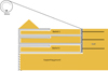 |
Fig. 4 Schematic representation of the inflight excavation device. Représentation schématique du dispositif d’excavation en vol. |
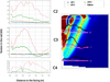 |
Fig. 5 (a) Prototype tensions from optic fibers measurements for a wall with 0.5 slenderness ratio. (b) Relative norm of strain tensor and tension force distributions along the nails (black at failure, pink after the lift 3). (a) Tensions prototypes mesurées à l’aide de fibres optiques pour un mur d’élancement 0,5. (b) Norme relative du tenseur des déformations et allure des efforts le long des clous (en noir à la rupture, en rose lors de l’enlèvement du panier 3). |
3 Influence of the slenderness ratio
As stated above, we call here slenderness ratio the ratio B/H between the length of the nails B and the height of the wall H. The deformation results observed through GeoPIV on centrifuge models revealed that the failure surface become more horizontal as the length of the nails increases (de Sauvage et al., 2021). It is as if the increase in nail length decreases the friction angle of an equivalent homogeneous bulk of soil. An impact of the slenderness ratio on settlements and wall tip displacement has also been highlighted (de Sauvage, 2018).
To further investigate the influence of slenderness ratio on the wall behaviour, a finite element numerical study has been carried out. It is fully presented in (de Sauvage, 2018). Different wall heights and different nail lengths were considered, leading to the slenderness ratios presented in Table 1.
As a result, the computed nail tension distribution at the facing depends on slenderness. For short nails, the tension of top nails is low and the distribution is pear-shaped, with a low belly. As the length of the nails increases, the tension of the top nails increases and the distribution becomes rounder. Thus, as the slenderness ratio B/H increases, the distribution of nail head forces at the end of the excavation process tends to move away from the distribution observed in the case of active earth pressure.
Figure 6a shows the evolution of nail head tensile forces for the wall (H, B) = (10.5, 6.5) as the excavation progresses. It displays a transition from the round to the pear-shaped distribution. After the fourth excavation, the height of the structure is 6 m so the slenderness ratio is greater than 1 and the distribution is round. The comparisons made between final distributions are also valid between different phases of the same wall. Similarly, the distributions calculated for (H, B) = (9, 6.5) and (H, B) = (10.5, 7.5) (not presented in this paper) are similar. They both correspond to slenderness ratios B/H = 0.72.
The shape of the nail head tensions distribution thus seems to depend on the slenderness ratio B/H and not on the excavation height. In order to check that, the nail head tensions are normalised and plotted as a function of the nail height normalised by the height of the wall. Figure 6b shows the normalized final distributions obtained for all the walls considered, with heights varying between 6 m and 10.5 m. The blue curves are calculated with slenderness ratios close to 0.6 and the red curves with a slenderness ratio equal to 1. With the same slenderness, the normalised distributions are identical whatever the height of the structure.
The numerical model allows to estimate the relative shear stress of the soil Sτ, defined as the ratio between the mobilized shear stress and the maximum shear capacity at the current confining pressure (See Eq. (1) where σ1 and σ3 are the minimal and maximal principal stresses, c the cohesion and ϕ the friction angle of the soil).
 (1)
(1)
It appears that for bulky walls, most of the soil is far from failure (relative shear stress lower than 1) and for slender walls, most of the soil in the Coulomb wedge is at the limit of failure (relative shear stress near 1). This is in accordance with the transition from the round distribution to the pear-shaped one which ultimately tends to the active earth pressure distribution.
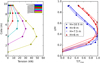 |
Fig. 6 (a) Evolution of the facing tensile forces during the excavation of a 10.5 m high nailed wall for 6.5 m nails. (b) Normalized facing tensile forces for walls of varying heights (6 to 10.5 m) and slenderness B/H = 1 (red) and B/H close to 0.6 (blue). (a) Évolution du profil des efforts au parement au cours de l’excavation d’un mur cloué de hauteur 10,5 m pour des clous de 6,5 m. (b) Profils normalisés des efforts au parement pour des murs de hauteur variable (6 à 10,5 m) et d’élancements B/H = 1 (en rouge) et B/H proche de 0, 6 (en bleu). |
4 Adaptation of the PROSPER method
The results obtained in this study argue for a design that considers the construction phasing and the slenderness of the soil-nailed wall. As mentioned above, in PROSPER, the contribution of nails is evaluated by imposing a relative displacement δ between the “active zone” and the “passive zone”. The greater the relative displacement δ, the greater the reaction forces induced in the nail and the more the nail is mobilized. It should be noted that the PROSPER code allows the introduction of a difference between the displacement δ at top and at the bottom of the failure surface, inducing a lower mobilization of the lower nails. However, this feature is never used due to a lack of knowledge about the variations of this displacement δ.
We have also shown that the behaviour of a soil-nailed wall depends largely on its slenderness ratio. More precisely, the slenderness ratio reflects the difference between the distribution of tension at the facing and the one which would take place in the case of active earth pressure without reinforcement. The mobilization of the nails, represented in Prosper by δ, can then be characterised by their reduced tension Tred defined as the ratio between their head tensile force and the active pressure that would be observed at their depth:
 (2)
(2)
In equation (2), z is the altitude of the nail head counted from the toe, Sν is the vertical spacing between nails, Sh is the horizontal one and Ka is the coefficient of active earth pressure and γ is the unit weight of the soil.
The distribution of the reduced tensions reflects the relative mobilization of the nails and will be used to describe the distribution of relative displacement δ in the PROSPER method. The nailed head tensile forces (see Fig. 6b) can be interpolated by a third order polynomial function (a lowest order would not allow to capture the transition from pear-shaped to round profile). The polynomial coefficients depend linearly on the slenderness ratio (R2 > 0.95) and we can thus express nail head tensile force as:
 (3)
(3)
Combining equations (2) and (3) one gets a distribution of nail mobilization which can be introduced in PROSPER. Finally, it should be noted that the distribution thus defined is a priori valid only for a homogeneous soil-nailed wall without batter angle or back slope. Moreover, it is, a priori, only valid for fixed soil characteristics.
5 Application to a real soil-nailed wall
An experimental soil-nailed wall has been realised in Bévenais (France) and is fully described in (de Sauvage and Rajot, 2018). It is 7.5 m high (5 lifts) and the average length of nails is 6.2 m, giving a slenderness ratio B/H equal to 0.83. The soil is homogeneous and consists of a clean gravel (8% fines) that is well graded and unsaturated. The water table, located 30 m below the natural ground, does not impact the study.
The Bévenais wall has been studied using PROSPER and considering five different failure surfaces (C1 to C5) chosen to study the geotechnical internal stability. Since there was an uncertainty on the soil cohesion, computations have been carried out with a 6 kPa cohesion and without cohesion. In a first step, for every curve, a homogeneous relative displacement δ was introduced along the failure surface. The distribution of the forces at the facing thus obtained according to the least stable curve (C2) and considering a target safety factor of 1.35 is shown in Figure 7. This profile is neither comparable to the measurements nor consistent with the common observation that the bottom nail tension is generally very small.
A relative displacement δ distribution has then been introduced using equations (2) and (3). The mobilizations of the nails are 100% for the nail 1, 54% for the nail 2, 44% for the nail 3, 29% for the nail 4 and 1% for the nail 5. The distribution of nail head tensions obtained in this way (Fig. 7) is closer to the experimental measurements, but the forces in the upper nails remain too low. This may be due to the absence of cohesion in the Bévenais wall, whereas the equations (2) and (3) were determined for a soil with a cohesion of 15 kPa in order to ensure the stability of the wall between the lift and the facing installation.
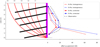 |
Fig. 7 Failure curves used in PROSPER and distribution of facing loading obtained by considering the least stable curve (C2) with or without cohesion, with or without homogeneous δ, and comparison with the measurements on the Bévenais wall. Courbes de ruptures utilisées dans PROSPER et répartition des efforts au parement obtenus en considérant la courbe la moins stable (C2) avec ou sans cohésion, avec δ homogène ou non et comparaison aux mesures sur le mur de Bévenais. |
6 Conclusions
The soil-nailed walls are traditionally designed using Limit Equilibrium methods inherited from the study of slope stability. Unfortunately, these methods generally fail to capture the real mobilization of the different nails. This has an impact on the design of the facing. A centrifuge study and a parametric finite element study were used to characterise the impact of the construction phase on the mobilization of nails and the influence of the ratio between the length of the nails and the height of the wall on the facing loading distribution. These lessons have made it possible to propose an improvement of the PROSPER method which, applied to a real structure, has significantly improved the determination of the facing loading. This result must now be generalised through the creation of more complete charts taking into account more complex geometries and variable mechanical characteristics of soils.
Acknowledgements
I want to express a huge thank to Thierry Dubreucq whose help was capital to achieve this work and to Jean-Pierre Rajot who supervised it. A big thank is also addressed to Fatima Tfayli who carried on lots of the centrifuge tests. This work would not have been possible without the French Ministry of Ecological Transition who funded it nor without the company NGE Fondations who built and funded the experimental wall.
References
- Buhan P de, Salençon J. 1993. A comprehensive stability analysis of soil nailed structures. Eur J Mech Series A Solids 12: 325. [Google Scholar]
- Byrne RJ, Cotton D, Porterfield J, Wolschlag C, Ueblacker G. 1996. Manual for design and construction monitoring of soil nail walls. Rapport Tech FHWA no SA-96-069. [Google Scholar]
- Coulomb CA. 1773. Essai sur une application des règles de maximis et minimis a quelques problèmes de statique relatif à l’architecture. Mem Div Sav Acad 7: 343–82. [Google Scholar]
- Delmas P, Cartier G, Abdelhedi A. 1986. Une nouvelle méthode de dimensionnement du clouage des pentes : programme Prosper. Bulletin de liaison des Laboratoires des Ponts et Chaussées 141. ISSN: 0458-5860. [Google Scholar]
- Frontard M. 1922. Cycloïdes de glissement des terres. Comptes rendus hebdomadaires Académie des Sciences, Paris 174: 526–528. [Google Scholar]
- Gassler G. 1987. Vernagelte Gelandesprunge-Tragverhalten und Standsicherheit. Doctoral thesis, University of Karlsruhe. [Google Scholar]
- Gigan JP. 1986. Applications du clouage en soutènement. Paramètres de conception et de dimensionnement des ouvrages. Bulletin de liaison des Laboratoires des Ponts et Chaussées 143: 51–64. [Google Scholar]
- Jacobsz SW. 2013. Centrifuge modelling of a soil nail retaining wall. J South Afr Inst Civil Eng 55(1): 85–93. [Google Scholar]
- Jacobsz SW, Phalanndwa TS. 2011. Observed axial loads in soil nails. In: Proceedings of the 15th African Regional Conference on Soil Mechanics and Geotechnical Engineering, pp. 221–227. [Google Scholar]
- Menkiti CO, Long M. 2008. Performance of soil nails in Dublin glacial till. Can Geotech J 45(12): 1685–1698. [Google Scholar]
- Mickovski SB, Lindsay FM, Smith MJ. 2016. Construction and testing of self-drilled soil nails. Proc Inst Civil Eng-Geotech Eng 169(6): 541–53. [CrossRef] [Google Scholar]
- Plumelle C. 1987. Expérimentation en vraie grandeur d’une paroi clouée. Revue Française de Geotechnique 40: 45–50. [CrossRef] [EDP Sciences] [Google Scholar]
- Raulin P, Rouquès G, Toubol A. 1974. Calcul de la stabilité des pentes en rupture non circulaire. Rapport Tech. 36. Laboratoire Central des Ponts et Chaussées. [Google Scholar]
- Rendulic L. 1935. Ein beitrag zur bestimmung der gleitsicherheit. Der Bauingenieur 16(19-20): 230–233. [Google Scholar]
- Salençon J. 1983. Calcul à la rupture et analyse limite. Presses de l’ENPC. [Google Scholar]
- Sauvage J de. 2018. Étude du comportement des murs de soutènement par clouage des sols en place : application au dimensionnement du parement. Thèse de doctorat, Université de Lyon. https://www.theses.fr/2018LYSET011. [Google Scholar]
- Sauvage J de, Rajot JP. 2018. Clouage des sols : conditions de long terme et amélioration du dimensionnement conventionnel. In : Journées Nationales de Géotechnique et de Géologie de l’Ingénieur, JNGG. [Google Scholar]
- Sauvage J de, Blanc M, Dubreucq T, Rajot J-P. 2019. Centrifuge modelling of a soil-nailed wall. In: Proceedings of the XVII ECSMGE-2019. [Google Scholar]
- Sauvage J de, Tfayli F, Dubreucq T, Rajot J-P. 2021. Modélisation sous macrogravité d’une paroi clouée respectant le phasage de construction. Revue Française de Geotechnique 166: 5. [CrossRef] [EDP Sciences] [Google Scholar]
- Schlosser F, Jacobsen HM, Juran I. 1984. Le renforcement des sols. Revue Française de Geotechnique 29: 7–33. [CrossRef] [EDP Sciences] [Google Scholar]
- Schlosser F, Plumelle C, Unterreiner P, Salençon J, Magnan JP. 1993. Recommendations Clouterre 1991. French National Research Project Clouterre (English translation). Paris: Presses de l’ENPC. ISBN: 2-85978-170-6. [Google Scholar]
- Shen CK, Kim YS, Bang S, Mitchell JF. 1982. Centrifuge modeling of lateral earth support. J Geotech Eng Div 108(9): 1150–64. [Google Scholar]
- Stanier SA, Blaber J, Take WA, White DJ. 2015. Improved image-based deformation measurement for geotechnical applications. Can Geotech J 53(5): 727–39. [Google Scholar]
- Stewart DI. 1989. Groundwater effects on in-situ walls in stiff clay. Doctoral thesis, University of Cambridge. [Google Scholar]
- Tei K. 1993. A study of soil nailing in sand. Doctoral thesis, University of Oxford. [Google Scholar]
- Tufenkjian MR, Vucetic M. 2000. Dynamic failure mechanism of soil-nailed excavation models in centrifuge. J Geotech Geoenviron Eng 126(3): 227–235. [CrossRef] [Google Scholar]
- Viswanadham BVS, Rotte VM. 2015. Effect of facing type on the behaviour of soil-nailed slopes: Centrifuge and numerical study. Discovery 46(215): 214–223. [Google Scholar]
Cite this article as: Jean de Sauvage. An adaptation of Limit Equilibrium Methods for the design of soil-nailed walls facings. Rev. Fr. Geotech. 2023, 175, 8.
All Tables
All Figures
|
Fig. 1 Construction phasing of a soil-nailed wall (Schlosser et al., 1993). Phasage de construction d’un mur en sol cloué (Schlosser et al., 1993). |
| In the text | |
|
Fig. 2 (a) Comparison of the stress profiles measured by Gassler and Plumelle. (b) Stress profiles measured on the walls instrumented by the FHWA (Byrne et al., 1996). Tmax is the maximal nail head tension on the wall height. (a) Comparaison des profils d’effort mesurés par Gassler et par Plumelle. (b) Profils d’efforts au parement mesurés sur les murs instrumentés par la FHWA (Byrne et al., 1996). Tmax est la tension au parement maximale mesurée sur la hauteur du mur. |
| In the text | |
|
Fig. 3 Principle for determining the contribution of nails in PROSPER. Principe de détermination de la contribution des clous dans PROSPER. |
| In the text | |
|
Fig. 4 Schematic representation of the inflight excavation device. Représentation schématique du dispositif d’excavation en vol. |
| In the text | |
|
Fig. 5 (a) Prototype tensions from optic fibers measurements for a wall with 0.5 slenderness ratio. (b) Relative norm of strain tensor and tension force distributions along the nails (black at failure, pink after the lift 3). (a) Tensions prototypes mesurées à l’aide de fibres optiques pour un mur d’élancement 0,5. (b) Norme relative du tenseur des déformations et allure des efforts le long des clous (en noir à la rupture, en rose lors de l’enlèvement du panier 3). |
| In the text | |
|
Fig. 6 (a) Evolution of the facing tensile forces during the excavation of a 10.5 m high nailed wall for 6.5 m nails. (b) Normalized facing tensile forces for walls of varying heights (6 to 10.5 m) and slenderness B/H = 1 (red) and B/H close to 0.6 (blue). (a) Évolution du profil des efforts au parement au cours de l’excavation d’un mur cloué de hauteur 10,5 m pour des clous de 6,5 m. (b) Profils normalisés des efforts au parement pour des murs de hauteur variable (6 à 10,5 m) et d’élancements B/H = 1 (en rouge) et B/H proche de 0, 6 (en bleu). |
| In the text | |
|
Fig. 7 Failure curves used in PROSPER and distribution of facing loading obtained by considering the least stable curve (C2) with or without cohesion, with or without homogeneous δ, and comparison with the measurements on the Bévenais wall. Courbes de ruptures utilisées dans PROSPER et répartition des efforts au parement obtenus en considérant la courbe la moins stable (C2) avec ou sans cohésion, avec δ homogène ou non et comparaison aux mesures sur le mur de Bévenais. |
| In the text | |
Current usage metrics show cumulative count of Article Views (full-text article views including HTML views, PDF and ePub downloads, according to the available data) and Abstracts Views on Vision4Press platform.
Data correspond to usage on the plateform after 2015. The current usage metrics is available 48-96 hours after online publication and is updated daily on week days.
Initial download of the metrics may take a while.