")
")
| Issue |
Rev. Fr. Geotech.
Number 158, 2019
Fondations d'éoliennes offshore
|
|
|---|---|---|
| Article Number | 3 | |
| Number of page(s) | 6 | |
| DOI | https://doi.org/10.1051/geotech/2019009 | |
| Published online | 2 septembre 2019 | |
Article De Recherche / Research Article
PISA: new design methods for offshore wind turbine monopiles
PISA : une nouvelle méthode de dimensionnement des monopieux de turbines éoliennes offshore
1
Department of Engineering Science, University of Oxford,
Oxford, UK
2
Department of Civil and Environmental Engineering, Imperial College London,
London, UK
3
Delft University, Netherlands, formerly University College Dublin,
Dublin, Ireland
* Corresponding author: Cette adresse e-mail est protégée contre les robots spammeurs. Vous devez activer le JavaScript pour la visualiser.
Abstract
This paper provides a summary of the PIle Soil Analysis (PISA) project, completed in the UK during the period 2013 to 2018. The research led to the development of a new, computationally efficient, one dimensional design model for laterally loaded monopile foundations, particularly for offshore wind turbine support structures. The current form of the design model is applicable to monotonic loading only, but it could form a basis for extensions to cyclic loading. This short paper describes the background to the project, outlining the key research elements completed, as well as the main impacts that have been achieved. A number of publications describing the research in further detail are highlighted.
Résumé
Ce document fournit un résumé du projet PIle Soil Analysis (PISA), réalisé au Royaume-Uni pendant la période 2013 à 2018. La recherche a conduit au développement d’un nouveau et efficace modèle de calcul monodimensionnel de fondations de type monopieux chargées latéralement, en particulier pour les structures supports d’éoliennes offshore. En l’état actuel, le modèle de calcul n’est applicable que pour les chargements mononotones, mais il pourrait servir de base pour une extension aux chargements cycliques. Ce bref article décrit le contexte du projet, soulignant les éléments clés obtenus lors de la recherche, ainsi que leurs principaux impacts. Plusieurs publications décrivant la recherche en détail sont citées.
Key words: Monopile / lateral / monotonic loading / design model
Mots clés : Monopieu / latéral / chargement monotone / modèle de calcul
© CFMS-CFGI-CFMR-CFG, Published by EDP Sciences 2019
1 Background
Offshore wind is central to decarbonising the world economy. 1200 by 10 MW wind turbines are consented to be designed and installed within 10 years around UK coastlines, with an expected capital expenditure of £30B to £45B. Additionally, ageing turbines will need to be replaced. The UK’s ambitions will grow in time; similar ambitions exist across Europe, USA, China, Taiwan and elsewhere around the world. This underlines the worldwide significance of the offshore wind market.
The foundations for wind turbine support structures, including installation, currently account for 20% to 30% of the overall costs. Optimisation of the design of the foundation, therefore, has the potential to support substantial improvements in wind farm economics. To address this opportunity, new design methods have been developed that reduce risk, design conservatism and costs associated with offshore wind turbine foundations. This research was concerned specifically with monopile foundations, which are large diameter steel tubes, impact driven into the seafloor, typically 8 to 10 m in diameter, 30 to 50 m long and weighing up to 1000 tonnes. The work revises conventional design approaches dating back 50 years, such as the API p-y method (API, 2010), with new and innovative ideas that facilitate the optimisation of foundations for specific geographic locations. By taking account of complex offshore site-specific ground conditions, lighter weight and more cost effective foundations can be developed. Indirect savings are also achieved as design risk can be better quantified.
2 The PISA project
The research described in this paper was conducted during a joint industry study known as the PISA (PIle Soil Analysis) project. Phase 1 of the work began in mid-2013; the project concluded at the end of Phase 2 in mid-2018. The scientific work was undertaken by an Academic Work Group (AWG) with members drawn from the University of Oxford and Imperial College London for both phases, and with University College Dublin contributing to Phase 1. The AWG collaborated closely with the industry partners − led by Ørsted and which included developers, contractors and consultants – through the Carbon Trust’s Offshore Wind Accelerator. Feedback and input was received during the project from technical experts representing the industry partners, as well as from an Independent Technical Review Panel. The project included a significant construction and testing component, with Socotec UK (formerly ESG) undertaking a medium scale pile testing campaign at two sites, to explore monopile behaviour for monotonic loading. Cyclic loading tests were also undertaken (not reported here) although developing a cyclic pile design method was not an objective of the PISA project.
3 Overview of work packages
Various elements of the PISA project are illustrated in Figure 1. A key aspect of the work was a suite of 28 medium scale field tests that were conducted to obtain experimental data on monopile behaviour, at a range of scales, at two different onshore test sites. To support the design of the field tests, a set of three dimensional (3D) finite element (FE) calculations were developed, to provide a priori predictions of the performance of the test piles. This finite element-modelling framework, once validated by the field-testing results, was used to conduct separate analyses of full-scale monopiles across a predefined parameter space. These finite element results provided a basis for the development and calibration of a simplified one-dimensional (1D) design model (also referred to as the “PISA design model”) to encode in a computationally efficient framework the fidelity of output of the finite element calculations. A general overview of the PISA project is given in Byrne et al. (2017, 2019a) and Burd et al. (2017).
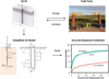 |
Fig. 1 Key elements of the PISA project. Éléments clés du projet PISA. |
3.1 Finite element modelling
State-of-the-art 3D finite element analyses, using the software ICFEP (Potts and Zdravković, 1999) were employed to underpin the PISA research. The numerical modelling approaches adopted in the work are described in Zdravković et al. (2015, 2019b) and Taborda et al. (2019).
Initially, finite element models were employed to support the design of the field-testing program. Following their successful validation against the field test results (Zdravković et al., 2019b, Taborda et al., 2019), the finite element models were used to develop and calibrate the PISA design model. In phase 1 of the work, the PISA design model was calibrated for two soil types (a glacial till known as Cowden clay and a marine sand, referred to as Dunkirk sand, at 75% relative density). These two soil types correspond to the soil conditions at the two field test sites. In phase 2 of the study, the design model calibration was expanded to include sands of different relative densities as well as a brittle stiff clay (London clay) and a soft clay (Bothkennar clay). A total of 88 monopile finite element calculations for 6 different homogeneous soil conditions as well as a range of pile geometries and loading conditions were employed to develop the PISA design model calibration database.
3.2 Field-testing
The field-testing program was executed by Socotec UK. Test sites at Cowden, UK (where the soil is stiff glacial clay till) and Dunkirk, France (dense marine sand) were adopted. Extensive geotechnical characterisation of these sites was conducted, including in situ testing and laboratory element testing (Zdravković et al., 2019a). The field-testing campaign involved 28 medium scale pile tests, with pile diameters 0.273, 0.762 and 2.0 m; different diameters were employed to investigate possible scaling effects. Detailed plans for the tests were developed, based on initial 3D finite element analyses (Byrne et al., 2015a). For many of the tests, the piles were loaded at 10 m above ground level to represent realistic loading conditions. Further details on the design of the field tests and the results that were obtained are given in Burd et al. (2019a), Byrne et al. (2019c) and McAdam et al. (2019).
The test piles were heavily instrumented, including with bonded fibre optic strain gauges (e.g. Doherty et al., 2015), which provided high-resolution measurement of strain for both monotonic and cyclic testing. The fibre optic gauges performed robustly through the impact driving installation process and during the different loading tests.
Figure 2 shows example field test data, for the performance of a 0.762 m diameter pile at the Cowden test site for both small (relevant for the fatigue limit state) and large (relating to the ultimate limit state) displacements. Also shown in Figure 2 are the 3D FE predictions for this pile test, and separate calculations conducted using the standard p-y method. It is clear that at both small and large displacements, the 3D finite element calculation provides a much closer representation of the field performance than the p-y method. This comparison provides confidence that well-calibrated finite element modelling can be used to predict, with good accuracy, the field behaviour of monopiles.
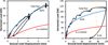 |
Fig. 2 Field test results from a 0.762 m diameter, L/D = 5.25, pile installed at Cowden. Small displacements (left) and large displacements (right). Résultats d’un essai sur site avec un pieu de 0,762 m de diamètre, L/D = 5,25, installé à Cowden. Petits déplacements (à gauche) et grands déplacements (à droite). |
3.3 PISA design model
Detailed interrogation of the 3D finite element results indicated that, as well as the lateral soil reaction that is incorporated in the standard p-y modelling approach, three additional soil reaction components are relevant for monopile foundations. These additional soil reactions are:
-
a distributed moment;
-
a base horizontal force;
-
a base moment.
These additional components, illustrated in Figure 1, become increasingly important as the pile diameter increases relative to the embedded length. The 3D finite element results facilitated a detailed calibration of parametric functions (referred to as “soil reaction curves”) to represent these four soil reaction components in the PISA design model. Further details on the formulation and calibration of the PISA design model are provided in Byrne et al. (2015b, 2017, 2019b) and Burd et al. (2017, 2019b). Analyses conducted using the PISA design model are rapid to compute. The model is therefore well-suited to monopile optimisation and offshore wind farm design, where there can be many individual foundations to design and many different load cases to consider.
3.4 Implementation for design
Two alternative approaches are proposed for calibrating the soil reaction curves employed in the PISA design model (Fig. 3). The first is a ‘‘rule-based method’’, in which lookup tables are used to defined appropriate inputs for the model, determined by basic strength and stiffness data; this approach is similar to current codified procedures. The second, more detailed approach, (referred to as the "numerical-based method") involves bespoke 3D finite element modelling to determine site-specific soil reaction curves. This is achieved by conducting a systematic 3D finite element study of pile response across an appropriate calibration space (e.g. L/D, M/HD, D/t etc, where L is embedded length, D is pile diameter, M is moment applied to the pile at ground level and H is the applied horizontal load); data from these calculations are then used to calibrate the PISA design model. Once calibrated, the 1D model is able to conduct rapid predictions of monopile behaviour, within the calibration space, that closely match the results that would be obtained with detailed 3D finite element analysis. The numerical-based PISA design approach has been implemented into commercial finite element software by PLAXIS, released in 2018 (PLAXIS, 2018).
The application of the PISA design model for some design conditions can lead to significant direct savings for the monopile foundation, compared with designs determined using current methods. For example, Figure 4 (left) illustrates the calibration space and the individual calibration pile cases adopted in the PISA project to calibrate the 1D model. To demonstrate the performance of the calibrated model, separate design cases were considered for parameters within the calibration space, but that differ from the actual calibration pile cases. Figure 4 (right) shows the results obtained for one of these design cases (a pile of diameter D = 8.75 m embedded in Cowden clay). As shown in the figure, the results from the 1D model compare closely to those obtained from an independent 3D FE analyses. Results obtained using the p-y method are also shown in Figure 4 (right). These results indicate that if design calculations are based on the p-y method, then the embedded pile length needs to be increased by about 2.2 diameters to achieve the same ultimate capacity (at a ground level displacement of 0.1D) that is predicted by the PISA design method. This design example indicates a substantial potential saving in pile length (and cost) in this particular case.
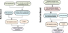 |
Fig. 3 The two design approaches for employing the PISA design method. Les deux approches de dimensionnement de la méthode PISA. |
 |
Fig. 4 Calibration analyses and design cases employed to calibrate and test the PISA design model (left). Analyses for a design case with L/D = 4, M/HD = 10 and D = 8.75 m embedded in a Cowden clay soil (right). Analyses de calibration et cas de dimensionnement utilisés pour calibrer et tester le modèle PISA (à gauche). Analyses pour un cas de dimensionnement avec L/D = 4, M/HD = 10 et D = 8,75 m, pieu dans l’argile de Cowden (à droite). |
4 Layered soils
After establishing the PISA design model for two homogeneous soils (Cowden clay and Dunkirk sand) a wider study in phase 2 was conducted to explore soil layering structures that are more likely to be encountered in the field. The influence of soil layers on the performance of the model was explored via the hypothesis; soil reaction curves calibrated using homogeneous soil profiles can be employed, directly, to conduct 1D analyses of monopiles embedded in a layered soil. Figure 5 illustrates the range of layering profiles considered during the study, involving various combinations of the homogeneous soils from the PISA database. A total 39 3D finite element calculations on layered soil combinations were completed. The computed response from the 1D model at both small and large reference displacements were found to be almost identical to those computed in the 3D analyses; the coefficient of variation was about 5% for small displacements and about 7% for large displacements, indicating a well-tuned model. For most of the layered soil configurations the original hypothesis held true. For a small number of cases involving combinations of very dense sand and very soft clay, however, the 1D calculations were found to be less accurate. For these configurations it appears that three-dimensional effects develop in the soil that are not captured by the 1D model. These findings suggest that for sites where layers of soil occur with highly contrasting strengths and stiffness, more detailed analysis is likely to be needed.
 |
Fig. 5 Phase 2 layered soil study soil profiles. Profils de sols considérés pour l’étude multicouche de la phase 2. |
5 Conclusions
This paper provides an overview of the new approaches for design of offshore wind turbine monopile foundations that were developed during the PISA project. The key research achievement was a new 1D design model (PISA design model) that captures the detailed soil-monopile interaction behaviour that is observed in more complex 3D analyses. This new design model facilitates site-specific and turbine-specific optimisation calculations. The PISA design model was developed from a range of activities including: numerical modelling, theoretical developments, soil element testing, site investigation and a comprehensive medium scale field pile testing campaign. Key outputs from the project include generic procedures for wind farm designers as well as sets of bespoke design equations. The close involvement of 10 industry partners, led by Ørsted, ensured that the research was focused on industry needs and this facilitated a rapid uptake of the project outputs. The work has now been reported through a number of conference and journal publications; key publications are listed in the References section below. Copies of PISA related publications are available on request from the lead Author.
Acknowledgements
The PISA Project was funded through the joint industry Offshore Wind Accelerator (OWA) program, designed and led by the Carbon Trust, with PISA phase 1 supported by the UK Department for Energy and Climate Change (DECC) and PISA phase 2 supported by the Scottish Government. The authors acknowledge the provision of financial and technical support by the following project partners: Ørsted (formerly DONG Energy, lead partner), E.ON, EDF, GE renewable energy (formerly through Alstom Wind), ScottishPower Renewables (formerly Iberdrola), Innogy, SSE, Statkraft (phase 1 only), Equinor (formerly Statoil), Van Oord and Vattenfall.
References
- API: RP 2A-WD. 2010. Recommended practice for planning, designing and constructing fixed offshore platforms. Washington: American Petroleum Institute. [Google Scholar]
- Burd HJ, Byrne BW, McAdam RA, et al. 2017. Design aspects for monopile foundations. Proceedings of TC209 Workshop: Foundation design of offshore wind structures, 19th ICSMGE, Seoul Korea (September). [Google Scholar]
- Burd HJ, Beuckelaers WJAP, Byrne BW, et al. 2019a. New data analysis methods for instrumented medium scale monopile field tests. Géotechnique. DOI: 10.1680/jgeot.18.pisa.002. [Google Scholar]
- Burd HJ, Taborda DMG, Zdravkovic L, et al. 2019b. PISA design model for monopiles for offshore wind turbines: application to a marine sand. Submitted. [Google Scholar]
- Byrne BW, McAdam RA, Burd HJ, et al. 2015a. Field testing of large diameter piles under lateral loading for offshore wind applications. Proceedings of the Sixteenth European Conference on Soil Mechanics and Geotechnical Engineering (XVI ECSMGE), Edinburgh, United Kingdom (September). [Google Scholar]
- Byrne BW, McAdam RA, Burd HJ, et al. 2015b. New design methods for large diameter piles under lateral loading for offshore wind applications. Proceedings of the Third International Symposium of Frontiers in Offshore Geotechnics (ISFOG 2015), Oslo, Norway (June). [Google Scholar]
- Byrne BW, McAdam RA, Burd HJ, et al. 2017. PISA: new design methods for offshore wind turbine monopiles. London UK: SUT OSIG 8th International Conference. [Google Scholar]
- Byrne BW, Burd HJ, Zdravkovic L, et al. 2019a. PISA design methods for offshore wind turbine monopiles. Houston, Texas: Offshore Technology Conference. [Google Scholar]
- Byrne BW, Houlsby GT, Burd HJ, et al. 2019b. PISA design model for monopiles for offshore wind turbines: application to a stiff glacial clay till. Submitted. [Google Scholar]
- Byrne BW, McAdam RA, Burd HJ, et al. 2019c. Monotonic laterally loaded pile testing in a stiff glacial clay till at Cowden. Géotechnique. DOI: 10.1680/jgeot.18.pisa.003. [Google Scholar]
- Doherty P, Igoe D, Murphy G, et al. 2015. Field validation of fibre Bragg grating sensors for measuring strain on driven steel piles. Géotechnique Lett 5: 74–79. [Google Scholar]
- McAdam RA, Byrne BW, Houlsby GT, et al. 2019. Monotonic laterally loaded pile testing in a dense marine sand at Dunkirk. Géotechnique. DOI: 10.1680/jgeot.18.pisa.004. [Google Scholar]
- PLAXIS MoDeTo. 2018. https://www.plaxis.com/software/plaxis-modeto/, accessed April 2019. [Google Scholar]
- Potts DM, Zdravković L. 1999. Finite element analysis in geotechnical engineering: theory. London: Thomas Telford. [CrossRef] [Google Scholar]
- Taborda DMG, Zdravković L, Potts DM, et al. 2019. Finite element modelling of laterally loaded piles in a dense marine sand at Dunkirk. Géotechnique, in press. DOI: 10.1680/jgeot.18.pisa.006. [Google Scholar]
- Zdravković L, Taborda DMG, Potts DM, et al. 2015. Numerical modelling of large diameter piles under lateral loading for offshore wind applications. Proceedings of the Third International Symposium of Frontiers in Offshore Geotechnics (ISFOG2015), Oslo, Norway (June). [Google Scholar]
- Zdravković L, Jardine RJ, Taborda DMG, et al. 2019a. Ground characterisation for PISA pile testing and analysis. Géotechnique. DOI: 10.1680/jgeot.18.pisa.001. [Google Scholar]
- Zdravković L, Taborda DMG, Potts DM, et al. 2019b. Finite element modelling of laterally loaded piles in a stiff glacial clay till at Cowden. Géotechnique. DOI: 10.1680/jgeot.18.pisa.005. [Google Scholar]
Cite this article as: Byron W. Byrne, Harvey J. Burd, Lidija Zdravković, Ross A. McAdam, David M.G. Taborda, Guy T. Houlsby, Richard J. Jardine, Christopher M. Martin, David M. Potts, Kenneth G. Gavin. PISA: new design methods for offshore wind turbine monopiles. Rev. Fr. Geotech. 2019, 158, 3.
All Figures
|
Fig. 1 Key elements of the PISA project. Éléments clés du projet PISA. |
| In the text | |
|
Fig. 2 Field test results from a 0.762 m diameter, L/D = 5.25, pile installed at Cowden. Small displacements (left) and large displacements (right). Résultats d’un essai sur site avec un pieu de 0,762 m de diamètre, L/D = 5,25, installé à Cowden. Petits déplacements (à gauche) et grands déplacements (à droite). |
| In the text | |
|
Fig. 3 The two design approaches for employing the PISA design method. Les deux approches de dimensionnement de la méthode PISA. |
| In the text | |
|
Fig. 4 Calibration analyses and design cases employed to calibrate and test the PISA design model (left). Analyses for a design case with L/D = 4, M/HD = 10 and D = 8.75 m embedded in a Cowden clay soil (right). Analyses de calibration et cas de dimensionnement utilisés pour calibrer et tester le modèle PISA (à gauche). Analyses pour un cas de dimensionnement avec L/D = 4, M/HD = 10 et D = 8,75 m, pieu dans l’argile de Cowden (à droite). |
| In the text | |
|
Fig. 5 Phase 2 layered soil study soil profiles. Profils de sols considérés pour l’étude multicouche de la phase 2. |
| In the text | |
Current usage metrics show cumulative count of Article Views (full-text article views including HTML views, PDF and ePub downloads, according to the available data) and Abstracts Views on Vision4Press platform.
Data correspond to usage on the plateform after 2015. The current usage metrics is available 48-96 hours after online publication and is updated daily on week days.
Initial download of the metrics may take a while.