")
")
| Issue |
Rev. Fr. Geotech.
Number 175, 2023
|
|
|---|---|---|
| Article Number | 4 | |
| Number of page(s) | 12 | |
| DOI | https://doi.org/10.1051/geotech/2023009 | |
| Published online | 23 octobre 2023 | |
Article de recherche / Research Article
Yield design-based analysis of reinforced soil structures, making use of different models of reinforced soils
Analyse par la théorie du calcul à la rupture d’ouvrages en sols renforcés, fondée sur différentes modélisations du sol renforcé
Laboratoire Navier, École des Ponts ParisTech, Université Gustave Eiffel, CNRS UMR 8205, 6-8 avenue Blaise Pascal, Cité Descartes, Champs-sur-Marne, 77455 Marne-la-Vallée Cedex 2, France
* Corresponding author: Cette adresse e-mail est protégée contre les robots spammeurs. Vous devez activer le JavaScript pour la visualiser.
Abstract
This contribution is aimed at applying the static and kinematic methods of the yield design theory, initially developed for homogeneous soils, to the stability analysis of reinforced soil structures. Several mechanical models of reinforced soils are considered to this end, starting from the mixed modelling approach which is the most intuitive one, according to which the reinforcements are treated as one-dimensional beam elements embedded in the soil regarded as a three-dimensional continuum. While this first model is posing some difficulties as regards the implementation of the lower bound static approach, a homogenization procedure should be preferred in the case of a dense array of regularly spaced inclusions, leading to the formulation of a macroscopic strength condition for the homogenized reinforced soil. Since the latter formulation, unlike the mixed modelling approach, fails to account for the shear and flexural strength characteristics of the reinforcements, a continuum multiphase description of reinforced soils, which may be considered as an extension of the previous homogenization method, has been developed. Such a multiphase model, which combines the advantages of the two previous models, is able to incorporate in an explicit way not only the shear and bending strength capacities of the reinforcements, but also a specific failure condition at the soil-inclusion interface. This contribution presents some illustrative applications of the yield design theory and related upper and lower bound methods to the design of typical reinforced soil structures, using the three above mentioned models.
Résumé
Cette contribution se propose d’examiner la mise en œuvre des méthodes statique et cinématique de la théorie du calcul à la rupture, initialement développées pour les sols homogènes, à l’analyse de la stabilité des ouvrages en sol renforcé. Plusieurs modélisations mécaniques du sol renforcé sont envisagées à cet effet, à commencer par l’approche de modélisation mixte qui est la plus intuitive, selon laquelle les inclusions de renforcement peuvent être traitées comme des éléments de poutres unidimensionnelles noyées dans le sol, considéré comme un continuum tridimensionnel. Tandis que cette première modélisation rencontre certaines difficultés concernant l’application de l’approche statique par l’intérieur, une procédure d’homogénéisation est à privilégier dans le cas d’un réseau dense d’inclusions régulièrement espacées, conduisant à la formulation d’un critère de résistance macroscopique pour le sol renforcé ainsi homogénéisé. Étant donné que cette dernière formulation, contrairement à l’approche de modélisation mixte, ne fait pas ressortir les caractéristiques de résistance au cisaillement et à la flexion des renforcements, une description multiphasique des sols renforcés, que l’on peut percevoir comme une extension de la méthode d’homogénéisation précédente, a été développée. Une telle modélisation multiphasique, qui combine les avantages des deux modélisations précédentes, est alors en mesure d’intégrer de manière explicite non seulement les capacités de résistance au cisaillement et à la flexion des renforcements, mais également un critère de résistance spécifique à l’interface sol-inclusion. Cette contribution présente quelques applications illustratives de la théorie du calcul à la rupture et des approches statiques par l’intérieur et cinématiques par l’extérieur associées, au dimensionnement d’ouvrages en sol renforcé typiques, pour lesquels les trois modélisations précédentes sont utilisées.
Key words: yield design / reinforced soils / upper and lower bound methods / mixed modelling approach / homogenization method / multiphase model
Mots clés : calcul à la rupture / sols renforcés / approches par l’extérieur et par l’intérieur / approche par modélisation mixte / méthode d’homogénéisation / modélisation multiphasique
© CFMS-CFGI-CFMR-CFG, 2023
1 Introduction
Most usual engineering design methods developed for reinforced soil structures are derived from classical stability analyses of homogeneous earthworks, such as slopes, embankments, retaining structures or shallow foundations. Indeed, these methods generally make use of failure surfaces, across which the resisting contribution of both the soil and the reinforcing inclusions are mobilized. In this context, the yield design theory provides a consistent mechanical framework for dealing with the stability of such reinforced geotechnical structures in a rigorous and efficient manner. The practical implementation of this theory relies upon two possible ways of modelling a reinforced soil, which are successively presented in this contribution.
In a first approach, called “mixed modelling” approach, the reinforcing inclusions are treated as one dimensional structural elements embedded in the soil regarded as a three dimensional continuum. This model may be easily incorporated into the upper bound kinematic method of yield design, either for “flexible” inclusions resisting to axial tensile forces only, or for “rigid” inclusions (such as large diameter piles) where the shear and bending resistances must also be taken into account.
On the other hand, in the case of soil reinforcement techniques involving a large number of regularly distributed inclusions, the use of a homogenization procedure appears to be an attractive alternative way to the mixed modelling approach, for performing the stability analysis of reinforced soil structures. According to this method, the composite reinforced soil may be regarded as a macroscopically homogeneous continuum, exhibiting anisotropic strength properties due to the preferential orientations of the linear reinforcements placed in the soil mass.
This contribution ends with the presentation of a multiphase model of reinforced soils developed in the context of yield design. This model, perceived as an extension of the homogenization concept, allows to include two important features in the stability analyses of reinforced soil structures: the shear and bending strength characteristics of the reinforcements, along with a specific soil-reinforcement interaction criterion.
2 The “mixed modelling” approach to the engineering design of reinforced soil structures
Most geotechnical structures involving inclusion-reinforced materials are commonly designed by resorting to an implicit mechanical model in which the material to be reinforced (soil, rock, etc.) is regarded as a 3D continuous medium, whereas the reinforcement inclusions (steel bars, piles or geomembranes) are treated as 1D (beams) or 2D (membranes or plates) structural elements. Hence the denomination of “mixed modelling”.
2.1 Outline of the “mixed modelling” approach in the context of yield design
This approach is simply derived from the civil engineer’s basic intuition facing the design of geotechnical earthworks reinforced by continuous linear inclusions. Two major characteristics are exploited to this end:
the volume fraction of the reinforcing material is small (metal or concrete for instance), if not very small, rarely exceeding a low percentage (< 5% in any case);
on the other hand, the reinforcing material exhibits much higher strength characteristics than those of the surrounding soil/rock material in which they are embedded, by a factor, which could be equal to several thousands (example of steel inclusions vs. soft soils).
As a consequence, owing to their strongly heterogeneous nature, such composite reinforced soil structures give rise to numerous difficulties, notably from a computational point of view, when trying for instance to set up reliable and efficient design methods for this particular kind of structures. The “mixed modelling” approach is specifically intended to circumvent such difficulties, by considering that the inclusions can be treated as one dimensional (or two dimensional in the case of reinforcing sheets or plates) structural elements, embedded in the matrix material described as a three dimensional continuous medium.
Referring for instance to Figure 1 which pictures a single inclusion incorporated into a ground mass subjected to plane strain conditions, the internal forces in the soil are classically modelled by means of a stress tensor field  , while the internal forces along the inclusion, modelled as a beam-like structural element, are described by either an axial force distribution N in the case of a “flexible” inclusion, or by a normal (N), shear force (V) and bending moment (M) distribution in the case a “stiff” inclusion. Note that in the case of plane strain conditions (Fig. 1), N and V have the dimension of forces per unit transverse length and M the dimension of a force (moment per unit transverse length).
Looking forward to applying the yield design theory to this kind of reinforced soil structures, the strength properties of both reinforced soil components should be specified by means of appropriate strength conditions, namely:
–on the one hand, the classical Mohr–Coulomb criterion for the soil:
 (1)
(1)
where σ1 (respectively σ3) denotes the major (resp. minor) principal component of  (tensile stresses are counted positive), c is the soil’s cohesion and ϕ its internal friction angle;
–on the other hand, the strength properties of the beam-like reinforcement may be expressed through a so-called “interaction formula” such as:
 (2)
(2)
where N0, V0 and M0 denote the strength of the inclusion subjected to a pure axial, shear and bending solicitation, respectively. In the case of “flexible” inclusions able to resist to axial tensile-compressive forces only, condition (2) reduces to:
 (3)
(3)
–in addition to the above mentioned criteria concerning both reinforced soil constituents, a strength condition involving the stresses exerted by the soil onto the inclusions ought to be specified.
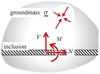 |
Fig. 1 Mechanical description of a reinforced soil according to the mixed modelling approach (plane strain conditions). Description mécanique d’un sol renforcé par l’approche de modélisation mixte (cas de la déformation plane). |
2.2 Implementation of the lower bound static approach of yield design
As regards the practical implementation of the lower bound static approach of the yield design theory, two situations should be considered.
2.2.1 Two-dimensional plane strain yield design analysis of reinforced soil structures
In the case when the stability analysis of a reinforced soil structure can be handled as a two-dimensional plane strain problem, where the soil is modelled as a two-dimensional continuum and the reinforcements as one-dimensional structural elements, the lower bound static approach of yield design can be implemented in a perfectly consistent way. Indeed, according to the general yield design reasoning, the stability of the structure is ensured, if a generalized stress field ( in the soil, (N,V,M) along the reinforcements: see Fig. 1) can be exhibited throughout the structure, which must verify the two following requirements:
the generalized stress field must be statically admissible with the applied loadings (weight of the soil, surface loadings, etc.), which means in particular that the equilibrium equations at any point of both the soil and the reinforcements must be satisfied (see a simple illustrative example in de Buhan et al., 2017);
the stress field
 should comply with the strength condition (1) at any point of the soil, while the distributions of (N,V,M) must satisfy the interaction formula (2) at any point of the reinforcements. Furthermore, in the case when the reinforcements are not perfectly bonded to the soil, an additional strength condition pertaining to the soil-reinforcements interaction should be considered in the analysis.
Since the analytical or semi-analytical implementation of the static lower bound approach turns out to be quite a complex task, especially for highly heterogeneous materials such as reinforced soils, an efficient treatment of such problems within a limited computational time, requires the use of numerical methods, such as the finite element method allowing the generation of the discretized stress fields, in conjunction with convex optimization procedures (see for instance https://optumce.com/products/optumg2/).
2.2.2 limitation to the 1D-3D mixed modelling approach
While, as previously shown, the static approach of yield design can be developed in a fully consistent mechanical framework for plane strain 1D-2D (or 2D-3D) problems, the most frequently encountered situation of linear inclusions distributed across a three dimensional continuous soil mass is posing a serious difficulty as regards the mere possibility of implementing such a static approach in the context of a 1D-3D mixed modelling, even if resorting to numerical procedures. Without going into a detailed argumentation (which may be found in de Buhan et al., 2017), this fundamentally comes from the fact that the stresses in the 3D continuous soil cannot be in equilibrium with the 1D distributions of (N,V,M) in the reinforcements, unless generating stress singularities in the vicinity of the linear inclusions, which would obviously no more satisfy a strength condition such as (1).
There are two possible ways of circumventing such a difficulty:
either by adopting a fully three dimensional description of both the soil and the reinforcements, which could however lead to hardly tractable complex problems, even by resorting to numerical methods, due to the strong heterogeneity of the reinforced soil;
or by resorting to a description of the composite reinforced soil as a homogenized continuum, which will be the subject of the third section of this contribution devoted to the homogenization approach.
2.3 Implementing the upper bound kinematic approach of yield design: an illustrative example
Therefore, the 1D-3D mixed modelling approach can only be adopted in the context of the kinematic approach of yield design, by considering appropriate virtual velocity fields (“failure mechanisms”). It should however be reminded (Salençon, 1990, 2013) that the yield design kinematic method provides upper bound estimates for the stability factor of structures, with absolutely no guarantee concerning a safe estimate for the actual value of this factor. A simple illustrative application of the upper bound kinematic approach, implemented in the framework of mixed modelling, is now presented.
2.3.1 Stability analysis of a reinforced vertical excavation: problem statement
A vertical cut of depth H, excavated in a homogeneous soil of cohesion c and friction angle ϕ, has been reinforced by one single layer of horizontal regularly spaced inclusions (“soil nailing” technique for instance: Fig. 2). The structure being subject to the soil specific weight γ in the absence of any other surcharge loading, the following non-dimensional factor may be introduced:
 (4)
(4)
so that the stability of the excavation, in the sense of the yield design theory, is ensured as far as this factor remains lower than or equal to a maximum critical value  :
:
 (5)
(5)
Under these conditions it appears, on the basis of simple dimensional analysis arguments, that this maximum critical value of the stability factor may be expressed as a function of the following non-dimensional strength parameters:
 (6)
(6)
where it should be noted that N, V and M denote the axial force, shear force and bending moment of the reinforcements per unit transverse length along the out-of-plane direction Oz.
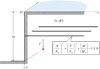 |
Fig. 2 Stability analysis of a vertical cut reinforced by one layer of horizontal inclusions. Analyse de stabilité d’un talus vertical renforcé par un lit d’inclusions horizontales. |
2.3.2 Implementing the kinematic method using a simple translational failure mechanism
Drawing inspiration from classical methods employed for investigating the stability of reinforced slopes, embankments or earth retaining structures, the kinematic approach of yield design may be implemented in a very simple way, by considering for instance rigid block failure mechanisms in which a triangular volume of reinforced soil such as OAB is given a rigid body translation. Such a mechanism induces a velocity jump across the boundary line AB, as well as at its intersecting point P with the reinforcement (Fig. 3).
Denoting by  the corresponding virtual velocity of the block OAB, the expression of the virtual work of external forces (gravity only) may be easily calculated as:
 (7)
(7)
where ψ is the angle made by the velocity  with AB.
According to the kinematic method of yield design, the latter quantity is to be compared with the maximum resisting work developed in the same mechanism. As it is classically shown (Salençon, 1990), this kind of mechanism leads to a non-trivial upper bound estimate for the ultimate stability factor of the reinforced cut, as far as the angle ψ made by the velocity jump with AB is comprised between ϕ and π−ϕ. The maximum resisting work is then additively decomposed in two terms relating to the discontinuity line AB in the soil, on the one hand, and to that induced by this discontinuity in the reinforcement at the intersecting point P, on the other hand. Leaving aside detailed calculations, which may be found in de Buhan and Salençon (1993), this maximum resisting work is equal to:
 (8)
(8)
Since the kinematic approach of yield design states that:
 (9)
(9)
The following upper bound estimate is obtained from (6) and (7), where ψ = ϕ:
 (10)
(10)
Hence, for α = π/4 − ϕ/2:
 (11)
(11)
where Kp = tan2 (π/4 + ϕ/2) is the usual passive earth pressure coefficient classically introduced in soil mechanics.
The method can be readily extended to “rotational” failure mechanisms such as that sketched in Figure 4, where a volume OAB of soil is given a rigid body rotation about point Ω, inducing a velocity jump not only in the soil along the failure line AB, but also at the intersecting point P of the reinforcement with the failure line, along with a discontinuity of the angular velocity. It is worth pointing out that in such rotational mechanisms, the flexural strength M0 of the reinforcements is mobilized in addition to their axial and shear strengths (N0,V0).
In the particular case whenψ = ϕ, the discontinuity line AB becomes an arc of log spiral of angle ϕ and focus Ω (arc of circle for a purely cohesive soil: ϕ = 0). Several computer codes dedicated to the engineering stability analysis of reinforced slopes, embankments or retaining walls are based upon the systematic use of such log spiral-based mechanisms (Anthoine, 1989, 1990; de Buhan et al., 1992; Simon, 2012).
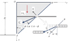 |
Fig. 3 Translational failure mechanism of the reinforced vertical cut. Mécanisme de bloc en translation du talus vertical renforcé. |
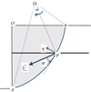 |
Fig. 4 Rotational failure mechanism used in the kinematic approach for analyzing the stability of a reinforced vertical excavation. Analyse de stabilité du talus vertical renforcé utilisant un mécanisme de bloc en rotation. |
2.3.3 To what extent should the reinforcement shear and bending strengths be taken into account in stability analyses?
One important point that is worth discussing concerns the way the strength of the reinforcing inclusions, and more specifically their resistance to shear (V0) and bending (M0) solicitations, should be taken into account in the abovementioned stability analyses making use of failure surfaces. Referring more specifically to soil nailed structures, this question had prompted a debate in the technical literature more than thirty years ago (Blondeau et al., 1984; Jewell and Pedley, 1990), in order assess how far the shear and bending strengths of the nails actually contribute to the stabilization of the soil structure. A comprehensive analysis performed within the rigorous and rational framework of yield design (de Buhan and Salençon, 1993), provides an adequate answer to this question. Its main results and conclusions are summarized in the sequel.
Indeed, as suggested by Figure 5a showing the actual failure pattern of a soil nailed excavation brought up to failure in a full scale experiment (Schlosser et al., 1993), the yield design kinematic approach may be generalized to more sophisticated failure mechanisms than simple rigid body motions, in which both the soil and the reinforcement undergo continuous deformations. Figure 5b displays such a mechanism where the velocity jump is replaced by a narrow “shear zone” in which the velocity remains continuous.
A parametric analysis has been undertaken on the example of a vertical cut made of a purely cohesive soil and reinforced by a network of n uniformly distributed horizontal nails (de Buhan and Salençon, 1993) (Fig. 6). Two kinds of failure mechanisms were considered to this end: rotational failure mechanisms with “slip circles” on the one hand, ring shaped “shear zones” on the other hand. The results of this analysis are gathered in Figure 6, showing the variations of different upper bound estimates for  as a function of the non-dimensional reinforcement factor R = n N0/2cH.
The following results are thus obtained:
curve n°1 is referring to the “slip circle” analysis in which both the shear and bending strengths of the nails are neglected (V0 = M0 = 0);
curve n°2 is associated to the same “slip circle” analysis where the following typical values for nails have been selected in the calculations:
 (12)
(12)
Finally, curve n°3 corresponds to the analysis making use of failure mechanisms of the second type (ring-shaped shear zones) with the same input data as for curve n°2.
The following conclusions may be drawn from analyzing these curves:
the comparison between curves n°1 and n°2 confirms what could be foreseen from the theory (and from common sense as well): using the same kind of mechanisms (involving velocity discontinuities only) and taking the shear and bending strength characteristics of the nails into account, leads to an increase of the upper bound estimate for the ultimate stability factor;
comparing curves n°2 and n°3 is even more significant. It shows that, once the shear and bending strengths of the nails are accounted for in the analysis, the evaluation of the ultimate stability factor is significantly improved (that is lowered) by the consideration of shear zone failure mechanisms (curve n°3). Furthermore, it turns out that those improved estimates are closer to those obtained in the case of “flexible” inclusions (curve n°1), than to those corresponding to curve n°2.
The above analysis suggests the possibility of setting up a simplified stability analysis procedure, in which failure mechanisms with velocity discontinuity surfaces could still be used, provided that sharply reduced shear strength capacities of the reinforcements be taken into account in the computation of the maximum resisting work. The initial strength condition (2) of the reinforcement should therefore be changed into the following “shear-truncated” one:
 (13)
(13)
where µ is a non-dimensional reduction factor, which may be estimated, notably from the size of the inclusion cross-section, such as its diameter.
Anyhow, leaving aside the case of reinforcing inclusions having large cross sectional dimensions, such as piles which will be considered later on and would need a specific investigation, it may be concluded that the additional maximum resisting contribution to the stability of reinforced soil structures which could be expected from the shear component developed in the reinforcements remains quite limited. So that in most cases, neglecting this contribution, which amounts to considering the reinforcements as “flexible” inclusions, only reduces the estimate of the ultimate stability factor by a small percentage, i.e. leads to a slightly conservative estimate.
 |
Fig. 5 (a) Experimental evidence of failure pattern of a soil nailed excavation involving a “shear zone” (Schlosser et al., 1993); (b) rotational failure mechanism involving an annular shear zone. (a) Mise en évidence expérimentale d’un mécanisme de rupture avec zone en cisaillement (Schlosser et al., 1993) ; (b) mécanisme de bloc en rotation mettant en jeu une zone annulaire en cisaillement. |
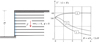 |
Fig. 6 Stability analysis of a uniformly reinforced vertical cut using rotational failure mechanisms with shear zones. Analyse de stabilité d’un talus vertical uniformément renforcé par des mécanismes de bloc en rotation avec zones en cisaillement. |
3 Yield strength properties of reinforced soils as anisotropic media: the homogenization approach
The homogenization method developed in this section provides an attractive alternative to the mixed modelling approach in the situation of densely reinforced soil structures. This method simply stems from the intuitive idea (which is quite natural for industrial composite materials) that, at the macroscopic scale of the whole structure, the composite reinforced soil may be regarded as an equivalent homogenous medium. Owing to the preferential orientation of the reinforcing inclusions, this homogenized continuous medium will undoubtedly exhibit anisotropic properties. Exploiting the fact that, due to the construction process, the reinforcing inclusions are regularly distributed throughout the soil, the homogenization method applied to periodic heterogeneous media will offer the fundamental theoretical framework for assessing the yield strength properties of such reinforced soils and devising correlative engineering design procedures.
3.1 Principle of the yield design homogenization method
The design of a vertically loaded surface footing of width B resting on a soil reinforced by a group of vertical inclusions may be considered for illustrative purpose. In the situation when the number of reinforcements becomes very large (up to several hundreds), evaluating the ultimate bearing capacity of this kind of geotechnical structure, is obviously a very complex, if not impossible task, requiring the mobilization of sophisticated computational capabilities. The homogenization approach may thus be conceived as an alternative engineering computational method. It amounts to replacing the initial bearing capacity problem shown in Figure 7a with the so-called equivalent homogenous problem sketched in Figure 7b.
The applicability of the periodic homogenization method relies upon two important conditions:
the reinforcing inclusions are placed into the soil following a regular arrangement, so that the reinforced soil may be treated as a periodic composite material;
the spacing s between two adjacent reinforcements is small in comparison with a characteristic length of the problem, such as the foundation’s width B (Fig. 7):
 (14)
(14)
where ε is a non-dimensional parameter, called scale factor.
First developed in the context of linear elasticity, almost forty years ago (Bensoussan et al., 1978; Sanchez Palencia, 1980), the method has been extended to the limit analysis or yield design context (Suquet, 1983; de Buhan, 1986). It relies upon the following fundamental result:
 (15)
(15)
where Q+ (respectively Qhom) is the ultimate load bearing capacity of the initial reinforced (resp. equivalent homogeneous) foundation. The above result is based on an appropriate definition of the macroscopic strength criterion of the periodically reinforced soil.
While several applications of the yield design homogenization method have been achieved concerning for instance foundation soil improvement by columnar inclusions, such as stone or lime columns (Jellali et al., 2007; Hassen et al., 2013; Guéguin et al., 2015), which cannot be adequately treated within the mixed modelling approach, the attention will now be focused on the particular, but frequently encountered case of thin highly resistant linear reinforcements (reinforced earth, soil nailing, micro piles…).
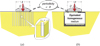 |
Fig. 7 Principle of the homogenization method applied to reinforced soil structures: example of a piled-raft foundation. Principe de la méthode d’homogénéisation appliquée aux ouvrages en sols renforcés : exemple d’un radier de fondation sur groupe de pieux. |
3.2 Formulation of a macroscopic strength condition for a soil reinforced by “thin” inclusions
The “reinforced earth” technique provides a very good example of a soil reinforced by a network of “thin” (metallic or polymeric) strips (Fig. 8). In this case, it may be shown (Mc Laughlin, 1972; Sawicki, 1983; de Buhan and Salençon, 1987; de Buhan et al., 1989; Michalowski and Zhao, 1996) that the macroscopic strength condition writes:
 (16)
(16)
In this definition,  is the unit vector parallel to the reinforcements, N0 the tensile resistance of each individual inclusion, S the cross sectional area of the representative volume of reinforced soil containing such an inclusion and
  denotes the soil’s strength condition such as the previously introduced Mohr–Coulomb condition (1). It is worth noting that the macroscopic strength condition reduces to the unreinforced soil strength condition when σ0 = 0.
The anisotropy of this criterion is geometrically illustrated in Figure 9 for a purely frictional soil (c = 0: dry sand for instance) under plane strain conditions in the (x−y)-plane with the reinforcements along the x-axis  . Indeed, as shown by this figure, the red colored domain of admissible macroscopic stresses may be drawn in the
  , as the convex envelope of the soil’s strength domain (blue colored circular cone with its apex at the origin) and that obtained through a translation equal to σ0 along the Σxx-axis.
This criterion can be easily incorporated in both the static and kinematic approaches of yield design, either analytically or numerically in the framework of a finite element formulation. By way of example, Figure 10 refers to the stability analysis of a retaining structure reinforced by a uniform density of horizontal strips, performed by means of three calculation methods: the upper bound kinematic approach using log-spiral mechanisms, as well as both static and kinematic methods of yield design incorporated into a finite element method (Abdi et al., 1994). The graph of the figure displays the different estimates obtained for the ultimate value of the reinforced structure stability factor K+ = (γH/c) +, as increasing functions of the soil’s friction angle ϕ ranging from 0° (purely cohesive soil) to 35°.
As it is clearly apparent from this graph:
the different analytical and numerical estimates are fairly close to each other since their relative gap remains between 2% and 5%, which implies that the exact theoretical value of K+ is captured within a very narrow margin;
the semi-analytical upper bound estimate
 derived from the use of log spiral rotational mechanisms are slightly better (i.e. lower) than those obtained by the finite element-based kinematic approach (
 ). This points to the excellent performance of this kind of mechanisms when used in the stability analysis of slopes or retaining structures.
 |
Fig. 8 Representative volume of a soil reinforced by strips made of a highly resistant material. Volume représentatif de sol renforcé par des armatures en matériau très résistant. |
 |
Fig. 9 Geometrical representation in the space of two-dimensional stresses of the macroscopic strength condition (15) for a purely frictional soil (c = 0). Représentation géométrique dans l’espace des contraintes bidimensionnelles du critère de résistance macroscopique (15) pour un sol pulvérulent (c = 0). |
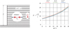 |
Fig. 10 Analytical and numerical estimates for the critical stability factor of a reinforced retaining structure using the homogenization method (Abdi et al., 1994). Bornes analytiques et numériques du facteur de stabilité extrême d’un ouvrage de soutènement renforcé utilisant la méthode d’homogénéisation (Abdi et al., 1994). |
4 The multiphase model as a generalization of the homogenization method
As can be seen from the closed form expression (15), the macroscopic strength condition for a soil reinforced by thin linear inclusions solely involves the axial strength of the inclusions as if they were “flexible”. A so-called multiphase model (de Buhan and Sudret, 1999; de Buhan and Hassen, 2010), perceived as an extension of the classical homogenization procedure, allows to account not only for the shear and bending strengths of the reinforcements, but also for a possible strength condition pertaining to soil-reinforcement interaction.
4.1 brief description of the multiphase model for a soil reinforced by linear inclusions
The concept of multiphase model of a reinforced soil stems from the basic intuition that this kind of composite material can be appropriately described as the superposition of two (and not only one as in the classical above described homogenization procedure) mutually interacting continua, called phases. Figure 11 represents for example in the particular case of two-dimensions (plane strain conditions), two distinct, but geometrically coincident, particles of soil and reinforcement phases, with their respective stresses in the (x1,x2)-plane. As it can be seen from this figure, where  represents the interaction force volume density, the generalized stresses in the reinforcement phase (representing the array of regularly spaced linear inclusions at the macroscopic scale) are denoted by (σr, τr, mr) which may be interpreted as the normal and shear forces, as well as bending moments, per unit area transverse to the reinforcement direction x1.
Within such a mechanical description, specific strength conditions can be assigned to the soil (condition (1)) and to the reinforcement phase, simply derived from (2);
 (17)
(17)
where it is worth noting that in the classical homogenization method (see Eq. (15)) the shear and bending strengths of the reinforcements are taken equal to zero:  . Moreover, an additional strength criterion, relative to the mutual interaction between the soil and the reinforcements, can be prescribed as:
 (18)
(18)
no such limitation being imposed when the soil and the reinforcements are assumed to be perfectly bonded. An example where such an interaction strength condition plays an important role in the stability of the reinforced soil structure is presented in Thai Son et al. (2009) or Hassen et al. (2021).
The multiphase model can thus be conceived as an improved homogenization method (Fig. 12), making it possible to incorporate not only the actual shear and flexural strength characteristics of the linear reinforcements, but also a specific failure condition at the soil-reinforcement interface. In other words, unlike the conventional homogenization method, this model is able to capture “scale effects” which may be attributed to the fact that the previously introduced scale factor ε = s/L is small, but not very small. This is for instance the case of a foundation involving a group of relatively few piles of large diameter, instead of a very large number of inclusions of very small diameter (Fig. 12).
 |
Fig. 11 Stresses involved in the two-dimensional multiphase description of a soil reinforced along the x1-axis. Contraintes mises en jeu dans le cadre d’une modélisation multiphasique bidimensionnelle d’un sol renforcé selon l’axe x1. |
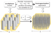 |
Fig. 12 The multiphase model as an extension of the homogenization approach. La modélisation multiphasique vue comme une extension de la méthode d’homogénéisation. |
4.2 Yield design of reinforced soil structures modelled as two-phase systems: an illustrative example
In this context, problems relating to the yield design analysis of reinforced geotechnical structures of any kind can be dealt with by both the static and kinematic methods, making use of analytical and/or numerical optimization techniques. Some typical examples of application may be found in (Thai Son et al., 2009, 2010), among which the most recent following one (Hassen et al., 2021) will be more specifically presented.
Figure 13 provides a general view of the geotechnical engineering design problem under consideration. An embankment resting upon a layer of soft clayey soil, which has been previously reinforced by a group of regularly spaced vertical piles, is subjected to an earthquake-induced lateral loading. According to the classical “pseudo-static” method, the seismic action on the structure is simply captured through a non-dimensional coefficient k so that the structure is submitted to a horizontal body force density kγ in addition to the constant vertical specific weight γ.
The analysis is focused on determining or more precisely evaluating the maximum value of k, denoted by k+, beyond which failure of the embankment would occur. Both the lower and upper bound methods are implemented numerically through a finite element formulation of the problem, where the pile reinforced zone located underneath the embankment is modelled as a two-phase system.
The curves drawn in Figure 14 show the variations of the numerically optimized bounds on the critical seismic coefficient k+, as increasing functions of the bending strength parameter  , all the other parameters, notably
  equal to 1 MPa, being kept constant. It turns out that the use of a refined mesh considerably improves the upper bound estimates (solid red line instead of dotted red line corresponding to a coarse fem mesh), which become very close to the lower bounds (solid blue line). Thus for
  , the upper bound estimate decreases from 0.191 (coarse mesh) to 0.161 (highly refined mesh), the relative difference with the lower bound estimate (0.158) dropping from 20% to 2%.
These results also show that it is useless to increase the bending resistance of the piles beyond a certain value since, as clearly shown in Figure 14, the numerical bounds do not increase any more. This observation is fully consistent with the fact that the corresponding optimal failure mechanism no longer concerns the pile-reinforced zone, but is located in the sole embankment. More precisely, the stability of the entire reinforced soil structure is governed by that of the lateral slope of the embankment as soon as  (see Hassen et al., 2021 for more details).
 |
Fig. 13 Seismic stability analysis of a piled embankment (Hassen et al., 2021). Analyse de stabilité sismique d’un remblai sur sol renforcé par inclusions rigides (Hassen et al., 2021). |
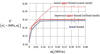 |
Fig. 14 Numerical upper and lower bound estimates for the critical seismic coefficient of a piled embankment as functions of the reinforcement bending strength parameter (Hassen et al., 2021). Majorants et minorants numériques du coefficient sismique critique du remblai sur inclusions rigides en fonction de la résistance en flexion des inclusions (Hassen et al., 2021). |
5 Conclusion
As it has been shown in this paper, far from being limited to geotechnical problems involving homogeneous (or multilayered) soils, the yield design theory is fully applicable to more complex soil structures where the native soil is reinforced by a more or less important number of inclusions. Two main categories of reinforcements ought to be considered from this point of view.
The case of soils improved by column-type inclusions, such as “lime” or “stone” columns placed into a soft foundation soil in order to enhance its ultimate bearing capacity. Since the strength characteristics of the column constituent material are not so much greater than those of the surrounding soil, this type of inclusion can hardly be modelled as one-dimensional structural beam. The yield design analysis should therefore be carried out, either by considering a purely three dimensional heterogeneous problem as far as very few columnar inclusions are involved, or by resorting to a homogenization procedure for a large number of regularly spaced inclusions, which requires the prior determination of a macroscopic anisotropic strength criterion.
The second situation, which has been more thoroughly examined in this contribution, concerns all the reinforcement techniques employing thin linear inclusions made of a high-strength metallic or polymeric material: reinforced earth technique, soil nailing or rock bolting, micro piles, pile-reinforced foundations, etc. Two models have been presented for the implementation of the yield design static and kinematic approaches to such reinforced soil structures: the fairly intuitive “mixed modelling” approach, on the one hand, the homogenization approach, which appears to be the most appropriate when dealing with a dense network of inclusions, on the other hand.
Even though some difficulties may arise when trying to apply the lower bound static method, the upper bound kinematic method is easily implementable in the frame of the mixed modelling approach, either analytically using for example classical failure surfaces, or numerically through a finite element discretization of the explored velocity fields. In this context, a key element of the analysis is the correct evaluation of the shear and bending strengths of the inclusions.
Based on the prior determination of a macroscopic anisotropic strength criterion for the reinforced soil, a homogenization procedure should be preferably considered as soon as a dense network of inclusions is involved, although this approach fails to capture the shear and flexural strength characteristics of the reinforcements. Fortunately, the adoption of a multiphase modelling of reinforced soil, briefly outlined in this contribution, makes it possible to overcome such a limitation. Furthermore, a specific failure condition pertaining to the soil-reinforcement interaction, can be easily accommodated in such an enriched version of the yield design homogenization method.
References
- Abdi R, de Buhan P, Pastor J. 1994. Calculation of the critical height of a homogenized reinforced soil wall: a numerical approach. Int J Numer Anal Meth Geomech 18: 485–505. [CrossRef] [Google Scholar]
- Anthoine A. 1989. Mixed modelling of reinforced soils in the framework of yield design. Comput Geotech 7: 67–82. [CrossRef] [Google Scholar]
- Anthoine A. 1990. Une méthode pour le dimensionnement à la rupture des ouvrages en sols renforcés. Rev Fr Geotech 50: 5–17. [CrossRef] [EDP Sciences] [Google Scholar]
- Bensoussan A, Lions JL, Papanicolaou G. 1978. Asymptotic analysis for periodic structures. North-Holland, Amsterdam. [Google Scholar]
- Blondeau F, Christiansen M, Guilloux A, Schlosser F. 1984. Talren : une méthode de calcul des ouvrages en sols renforcés. In: Int Colloq on In Situ Soil Reinforcement, Presses de l’ENPC. [Google Scholar]
- de Buhan P. 1986. Approche fondamentale du calcul à la rupture des ouvrages en sols renforcés. Thèse d’État, Université Pierre et Marie Curie. [Google Scholar]
- de Buhan P, Hassen G. 2010. Macroscopic yield strength of reinforced soils: from homogenization theory to a multiphase approach. C R Acad Sci 338: 132–138. [Google Scholar]
- de Buhan P, Salençon J. 1987. Analyse de la stabilité des ouvrages en sols renforcés par une méthode d’homogénéisation. Rev Fr Geotech 41: 29–43. [CrossRef] [EDP Sciences] [Google Scholar]
- de Buhan P, Salençon J. 1993. A comprehensive stability analysis of soil nailed structures. Eur J Mech, A/Solids 12(3): 325–345. [Google Scholar]
- de Buhan P, Sudret B. 1999. A two-phase elastoplastic model for unidirectionally reinforced materials. Eur J Mech, A/Solids 18(6): 995–1012. [Google Scholar]
- de Buhan P, Dormieux L, Salençon J. 1992. An interactive computer software for the yield design of reinforced soil structures. In: Int. Coll. « Informatique et Géotechnique », Paris. [Google Scholar]
- de Buhan P, Mangiavacchi R, Nova R, Pelligrini G, Salençon J. 1989. Yield design of reinforced earth retaining walls though a homogenization method. Geotechnique 39: 189–201. [CrossRef] [Google Scholar]
- de Buhan P, Bleyer J, Hassen G. 2017. Elastic, plastic and yield design of reinforced structures. London: ISTE-Elsevier. [Google Scholar]
- Guéguin M, Hassen G, de Buhan P. 2015. Stability analysis of homogenized stone column reinforced foundations using a yield design numerical approach. Comput Geotech 64: 10–19. [CrossRef] [Google Scholar]
- Hassen G, Guéguin M, de Buhan P. 2013. A homogenization approach for assessing the yield strength properties of stone column reinforced soils. Eur J Mech, A/Solids 37: 266–280. [Google Scholar]
- Hassen G, Donval E, de Buhan P. 2021. Numerical stability analysis of reinforced soil structures using the multiphase model. Comput Geotech 133: 104035. [CrossRef] [Google Scholar]
- Jellali B, Bouassida M, de Buhan P. 2007. A homogenization approach to estimate the ultimate bearing capacity of a stone column reinforced foundation. Int J Geotech Eng 1: 61–69. [CrossRef] [Google Scholar]
- Jewell R, Pedley JM. 1990. Soil nailing design: the role of bending stiffness. Ground Eng: 30–36. [Google Scholar]
- Mc Laughlin PV. 1972. Plastic limit behavior and failure of filament reinforced materials. Int J Solids Struct 8: 1299–1318. [CrossRef] [Google Scholar]
- Michalowski PV, Zhao A. 1996. Failure of fiber-reinforced granular soils. J Geotech Eng, ASCE 122(3): 226–234. [Google Scholar]
- Salençon J. 1990. An introduction to the yield design theory and its application to soil mechanics. Eur J Mech, A/Solids 9(5): 477–500. [Google Scholar]
- Salençon J. 2013. Yield design. Wiley-ISTE. [CrossRef] [Google Scholar]
- Sanchez Palencia E. 1980. Non homogeneous media and vibration theory. In: Lectures Notes in Physics 127. Berlin: Springer-Verlag. [Google Scholar]
- Sawicki A. 1983. Plastic limit behavior of reinforced earth. J Geotech Eng, ASCE 109: 1000–1005. [Google Scholar]
- Schlosser J, Unterreiner P, Plumelle C. 1993. Validation of calculation methods of soil nailed walls based on the experimentations of the National Project CLOUTERRE. Rev Fr Geotech 64: 11–20. [CrossRef] [EDP Sciences] [Google Scholar]
- Simon B. 2012. Yield design applied to earth retaining structures. In: Proc Indian Geotech Conf, New Dehli. [Google Scholar]
- Suquet P. 1983. Analyse limite et homogénéisation. C R Acad Sci, Paris 296(série II): 1355–1358. [Google Scholar]
- Thai Son Q, Hassen G, de Buhan P. 2009. A multiphase approach to the stability analysis of reinforced earth structures accounting for a soil-strip failure condition. Comput Geotech 36: 454–462. [CrossRef] [Google Scholar]
- Thai Son Q, Hassen G, de Buhan P. 2010. Seismic stability analysis of piled embankments: a multiphase approach. Int J Numer Anal Meth Geomech 34: 91–110. [CrossRef] [Google Scholar]
Cite this article as: Patrick de Buhan. Yield design-based analysis of reinforced soil structures, making use of different models of reinforced soils. Rev. Fr. Geotech. 2023, 175, 4.
All Figures
|
Fig. 1 Mechanical description of a reinforced soil according to the mixed modelling approach (plane strain conditions). Description mécanique d’un sol renforcé par l’approche de modélisation mixte (cas de la déformation plane). |
| In the text | |
|
Fig. 2 Stability analysis of a vertical cut reinforced by one layer of horizontal inclusions. Analyse de stabilité d’un talus vertical renforcé par un lit d’inclusions horizontales. |
| In the text | |
|
Fig. 3 Translational failure mechanism of the reinforced vertical cut. Mécanisme de bloc en translation du talus vertical renforcé. |
| In the text | |
|
Fig. 4 Rotational failure mechanism used in the kinematic approach for analyzing the stability of a reinforced vertical excavation. Analyse de stabilité du talus vertical renforcé utilisant un mécanisme de bloc en rotation. |
| In the text | |
|
Fig. 5 (a) Experimental evidence of failure pattern of a soil nailed excavation involving a “shear zone” (Schlosser et al., 1993); (b) rotational failure mechanism involving an annular shear zone. (a) Mise en évidence expérimentale d’un mécanisme de rupture avec zone en cisaillement (Schlosser et al., 1993) ; (b) mécanisme de bloc en rotation mettant en jeu une zone annulaire en cisaillement. |
| In the text | |
|
Fig. 6 Stability analysis of a uniformly reinforced vertical cut using rotational failure mechanisms with shear zones. Analyse de stabilité d’un talus vertical uniformément renforcé par des mécanismes de bloc en rotation avec zones en cisaillement. |
| In the text | |
|
Fig. 7 Principle of the homogenization method applied to reinforced soil structures: example of a piled-raft foundation. Principe de la méthode d’homogénéisation appliquée aux ouvrages en sols renforcés : exemple d’un radier de fondation sur groupe de pieux. |
| In the text | |
|
Fig. 8 Representative volume of a soil reinforced by strips made of a highly resistant material. Volume représentatif de sol renforcé par des armatures en matériau très résistant. |
| In the text | |
|
Fig. 9 Geometrical representation in the space of two-dimensional stresses of the macroscopic strength condition (15) for a purely frictional soil (c = 0). Représentation géométrique dans l’espace des contraintes bidimensionnelles du critère de résistance macroscopique (15) pour un sol pulvérulent (c = 0). |
| In the text | |
|
Fig. 10 Analytical and numerical estimates for the critical stability factor of a reinforced retaining structure using the homogenization method (Abdi et al., 1994). Bornes analytiques et numériques du facteur de stabilité extrême d’un ouvrage de soutènement renforcé utilisant la méthode d’homogénéisation (Abdi et al., 1994). |
| In the text | |
|
Fig. 11 Stresses involved in the two-dimensional multiphase description of a soil reinforced along the x1-axis. Contraintes mises en jeu dans le cadre d’une modélisation multiphasique bidimensionnelle d’un sol renforcé selon l’axe x1. |
| In the text | |
|
Fig. 12 The multiphase model as an extension of the homogenization approach. La modélisation multiphasique vue comme une extension de la méthode d’homogénéisation. |
| In the text | |
|
Fig. 13 Seismic stability analysis of a piled embankment (Hassen et al., 2021). Analyse de stabilité sismique d’un remblai sur sol renforcé par inclusions rigides (Hassen et al., 2021). |
| In the text | |
|
Fig. 14 Numerical upper and lower bound estimates for the critical seismic coefficient of a piled embankment as functions of the reinforcement bending strength parameter (Hassen et al., 2021). Majorants et minorants numériques du coefficient sismique critique du remblai sur inclusions rigides en fonction de la résistance en flexion des inclusions (Hassen et al., 2021). |
| In the text | |
Current usage metrics show cumulative count of Article Views (full-text article views including HTML views, PDF and ePub downloads, according to the available data) and Abstracts Views on Vision4Press platform.
Data correspond to usage on the plateform after 2015. The current usage metrics is available 48-96 hours after online publication and is updated daily on week days.
Initial download of the metrics may take a while.